ABP Scaffolding ABP Scaffolding

How to Perform a Jobsite Visual Inspection of Used Couplers?

Time:2026-09-15 Author:Madeline
0%

Before a second-hand coupler lifts another bucket, its condition must be verified, not assumed. This guide explains how to perform a jobsite visual inspection on second-hand couplers using practical checks, manufacturer guidance, and documented safety principles. The inspection begins with the identification plate, service history, attachment compatibility, and visible damage around the frame, pins, locking mechanism, and welds.

The U.S. Bureau of Labor Statistics reported 1,075 fatal work injuries in construction during 2023. OSHA also identifies struck-by and caught-in hazards among construction’s major risks. A defective coupler can increase both risks when a bucket shifts, unlocks, or separates unexpectedly. Look closely at hydraulic hoses, fittings, cylinders, retaining pins, safety indicators, and locking wedges. Fresh paint can hide old cracks. Rust around a pin bore can signal movement, not simple age. A quick look is tempting. It is not enough.

Human-factors expert James Reason wrote, “We cannot change the human condition, but we can change the conditions under which humans work.” That principle applies directly here. A competent inspector should clean critical areas, compare wear with the manufacturer’s limits, and photograph questionable defects. Any coupler showing cracking, serious deformation, excessive play, leakage, or unclear locking status should be isolated until a qualified person evaluates it. Visual inspection cannot reveal every internal defect. That limitation matters. This article offers a disciplined starting point, not permission to rely on guesswork.
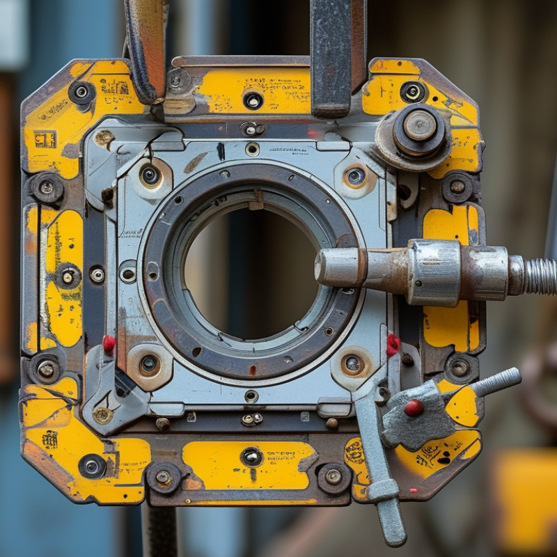
How to Perform a Jobsite Visual Inspection of Used Couplers?

Define the Coupler’s Role and Inspection Scope

A used coupler is not merely a quick connection device. It transfers working forces between the machine and attachment, while retaining the attachment during lifting, digging, or grading. Define that role before inspecting anything. The operator’s manual, coupler identification plate, and site task plan should confirm its intended attachments, locking method, and load limits.

The inspection scope must include the coupler, attachment interface, machine connection points, hydraulic lines, locking pins, safety indicators, and surrounding work area. Remove soil and grease first. Look for oval pin holes, cracked welds, bent retainers, damaged hoses, and missing locking components. Operate the locking system only in a controlled position. Never rely on a visual indicator alone. A pin may appear engaged while debris prevents full seating.

This discipline matters beyond one attachment. The U.S. Bureau of Labor Statistics reported 1,075 fatal work injuries in construction during 2023. The figure does not prove couplers caused those incidents, but it reinforces the need for defined inspection boundaries. HSE reported 51 fatal injuries to construction workers in Great Britain during 2023/24. A practical weakness remains common: inspectors often check the coupler but overlook the attachment’s receiving points. I have seen clean-looking assemblies hide wear beneath packed clay. Record photographs, measurements, defects, and corrective actions. If the locking function feels abnormal, stop the task and obtain competent technical assessment.

How to Perform a Jobsite Visual Inspection of Used Couplers?

Define the Coupler’s Role and Inspection Scope

Inspection scope allocation: The chart prioritizes the field inspection areas that directly affect a used coupler’s ability to connect, retain, and safely support an attachment. Structural damage and locking-system condition receive the greatest emphasis because failures in these areas can result in attachment separation.

Before use, confirm the coupler’s intended role and compatibility with the host machine and attachment. Check the frame, pins, locking wedges or hooks, hydraulic components, welds, wear surfaces, visible cracks, deformation, unauthorized repairs, and required safety documentation. Any defect affecting positive engagement or retention should be treated as a stop-use condition until evaluated by a competent person.

Prepare Safe Access, Tools, and Inspection Records

How to Perform a Jobsite Visual Inspection of Used Couplers?

Prepare Safe Access, Tools, and Inspection Records

A safe inspection begins before anyone touches a used coupler. Check the access route, ground condition, lighting, and nearby moving equipment. Use a stable platform, suitable footwear, and fall protection where required by the site plan. Never inspect from an unstable stack or improvised position. Safety comes first.

Carry a clean flashlight, wire brush, measuring tool, inspection mirror, gloves, and a camera. Remove loose dirt carefully, but do not force seized parts during a visual check. Examine threads, pins, bolts, nuts, locking surfaces, and body edges. Look for cracks, distortion, heavy corrosion, missing parts, and fresh impact marks. Compare suspicious damage with the approved equipment criteria or service guidance.

Record the identification number, inspection date, location, and inspector’s name. Add clear photographs with a scale beside the defect. Describe what you saw, not what you assume. A note saying “damaged” is weak; “six-millimeter crack near the bolt housing” is useful. Mark questionable couplers and separate them from accepted stock until a qualified person reviews them.

I have found that rushed records create more uncertainty later. That mistake is easy to repeat. Review each entry before leaving the area, and record weather or access problems that may have limited the inspection.

Examine the Coupler’s Structure and Connection Points

How to Perform a Jobsite Visual Inspection of Used Couplers?

Examine the coupler’s structure before checking its attachment. Park the machine safely and clean away packed soil, grease, and rust flakes. Dirt can conceal cracks around the side plates, nose, and locking housing. Use a flashlight, mirror, and straightedge when visibility is poor.

Look closely at welds. Hairline cracks, widened seams, or fresh grinding marks deserve attention. Compare both sides of the coupler. Uneven wear may indicate twisting or poor alignment. Check the pin bores for oval shapes, deep scoring, and displaced bushings. Inspect the attachment pins too. They should seat fully without visible gaps or excessive movement. Examine locking pins, springs, hydraulic cylinders, hoses, and retaining hardware. The connection points carry concentrated loads, so small damage can become serious during lifting or digging.

The U.S. Bureau of Labor Statistics recorded 1,032 fatal injuries in construction and extraction occupations during 2023. That figure does not isolate coupler failures, but it reinforces the need for disciplined checks. A coupler may look serviceable while its locking indicator is partly engaged. That is an easy mistake. I would stop the inspection when visibility remains uncertain, rather than guess. Record photographs, measurements, and defects before use. Do not rely on paint, recent grease, or a smooth appearance as proof of structural integrity.ագիտական

How to Perform a Jobsite Visual Inspection of Used Couplers? – Examine the Coupler’s Structure and Connection Points
Inspection Area What to Examine Visual Inspection Method Acceptable Condition Typical Disposition
Coupler Body and Frame Check the main frame, side plates, welds, corners, and mounting surfaces for cracks, bending, distortion, or heavy impact marks. Clean off loose soil and inspect under good lighting. Compare both sides for symmetry and look for fresh metal, stretched paint, or opened weld lines. The frame remains straight, with no visible cracks, structural separation, severe deformation, or damage that could affect attachment alignment. Pass if sound
Welded Joints Inspect weld beads around brackets, ears, hooks, retaining features, and high-load connection areas. Use a scraper or wire brush where needed. Examine for linear cracks, undercutting, porosity, incomplete fusion, or repaired areas. Welds are continuous and free from visible cracking, separation, or significant undercutting. Repairs are documented and professionally completed. Review repair
Mounting Pins Check the primary and secondary pins for bending, scoring, corrosion, mushroomed ends, damaged retaining grooves, or excessive movement. Visually inspect exposed pin surfaces and retaining areas. With the attachment safely supported, check for abnormal looseness without placing hands in pinch points. Pins are straight, properly seated, and retained. Contact surfaces are not deeply grooved or visibly undersized. Pass if secure
Bushings and Pin Bore Areas Look for oval-shaped bores, excessive clearance, worn bushings, cracks around bores, and metal deformation caused by loose pins. Inspect the full circumference of each bore. Compare the amount of visible clearance between corresponding connection points. Bores are round and intact, with no cracking or obvious ovality. Clearance is within the equipment or attachment manufacturer’s specified limit. Measure if worn
Locking Jaws, Hooks, or Wedges Examine engagement surfaces for rounding, chips, deformation, material loss, embedded debris, or incomplete movement. Operate the locking mechanism only when the machine is isolated and the attachment is supported. Observe the complete open-to-locked travel. Locking components move fully, engage the attachment connection points evenly, and show no visible damage that could allow unintended release. Do not use if faulty
Retaining Pins, Clips, and Safety Devices Verify that all retaining pins, keepers, clips, locking tabs, and secondary retention devices are present and undamaged. Compare each connection point with the coupler’s parts diagram or approved inspection procedure. Check that retainers cannot fall out during normal operation. Every required retaining device is installed, correctly seated, and free from bending, cracking, severe corrosion, or unauthorized substitutes. Stop if missing
Hydraulic Cylinder and Rod For hydraulic couplers, inspect the cylinder barrel, rod, seals, mounting eyes, and rod surface for leaks, dents, scoring, or bending. Clean the area and look for fresh oil film or drips. Never use fingers to locate a suspected hydraulic leak; use suitable inspection methods and keep clear of pressurized fluid. No active leakage, damaged rod surface, bent cylinder component, or loose cylinder mounting connection is visible. Isolate if leaking
Hydraulic Hoses and Fittings Inspect hoses for cuts, abrasion, crushed sections, exposed reinforcement, blistering, twisting, and damaged fittings or protective sleeves. Follow each hose from the cylinder to the machine connection. Check routing, bend radius, clamp condition, and clearance from moving or hot parts. Hoses are dry, correctly routed, securely supported, and free from exposed reinforcement, severe abrasion, or damaged fittings. Replace if damaged
Connection Interface Confirm that the coupler’s hooks, pin seats, jaw faces, or adapters match the intended attachment and are not obstructed by dirt, weld buildup, or deformation. Inspect the interface before connecting. Test-fit only according to the approved procedure and keep personnel outside the attachment’s drop and pinch zones. Connection points align correctly and allow full seating without forcing, excessive gaps, or contact with damaged areas. Verify fit
Fasteners and Bolted Connections Check bolts, nuts, washers, and threaded areas for looseness, missing hardware, damaged threads, corrosion, or signs of movement. Look for shifted bolt heads, fretting marks, elongated holes, and damaged locking features. Torque verification should follow the approved specification. Correct hardware is installed, seated, and secured. No fastener is missing, visibly loose, severely corroded, or stripped. Torque check
Wear Plates and Contact Surfaces Inspect high-contact surfaces for excessive wear, sharp edges, deep grooves, thinning, or uneven material loss. Clean the surfaces and compare wear on opposing sides. Measure thickness or wear limits when visual signs indicate significant material loss. Wear is even and remains within the approved service limit. Contact surfaces still support stable, full engagement. Measure limit
Corrosion and Contamination Look for deep rust pitting, chemical damage, hardened dirt, stones, weld spatter, or debris around moving and locking components. Remove loose contamination before inspection. Pay special attention to pin bores, locking cavities, spring areas, and hydraulic fittings. Surface corrosion is minor and does not reduce structural thickness or restrict movement. Critical areas are clean and unobstructed. Clean and reassess
Functional Engagement Check After the visual inspection, confirm that the coupler fully engages, locks, and remains secured to the compatible attachment. Use the machine’s approved operating procedure. Conduct the check from a safe position and perform the required visual or indicator confirmation before lifting. The attachment is fully seated and locked, with all required indicators or secondary checks confirming secure engagement. Stop if uncertain
Inspection Record Record the inspection date, equipment identification, coupler type, visible defects, corrective actions, and person completing the inspection. Use the site inspection form or maintenance log. Attach photographs and measurements for cracks, wear, repairs, or recurring defects. The record is complete, traceable, and reviewed before the used coupler is returned to service. Document result
Safety note: A visual inspection does not replace the manufacturer’s service limits, qualified maintenance inspection, non-destructive examination, or required functional testing. Remove the coupler from service when a crack, structural deformation, missing retention device, hydraulic leak, or uncertain locking condition is found.

Check Hydraulic, Mechanical, and Locking Components

How to Perform a Jobsite Visual Inspection of Used Couplers?

Before using a used coupler, I walk around it slowly and inspect it under good light. A clean surface can mislead me. Dirt may hide hairline cracks, fresh welds, or hydraulic damage. I check the body, mounting area, pins, and attachment interface for distortion. Any uneven gap or sharp edge deserves attention. I also compare both sides because wear is not always symmetrical.

Check Hydraulic, Mechanical, and Locking Components

For hydraulic systems, inspect hoses for cuts, bulges, abrasion, and wet fittings. A small oil stain can indicate a developing leak. Never touch suspected leaks with bare fingers. Examine cylinders and connectors for dents or loose seals. Mechanically, check pins, bushings, retaining clips, and grease points. Excessive movement suggests wear. The locking system needs special care. Confirm that locking pins move fully, springs respond, and the engagement indicator is visible. Test only through the approved procedure, with the attachment supported safely and no one nearby.

Tips: Use a flashlight and a clean rag. Take close photographs of questionable areas. Read the coupler’s service instructions before testing it. I sometimes focus too much on obvious rust and overlook worn bushings. That mistake is easy to repeat. If a lock does not seat clearly, stop the inspection and ask a qualified technician to assess it. Do not rely on appearance alone. Functional verification matters.

Record Defects and Determine Safe Reuse or Replacement

A used coupler can look serviceable while hiding a serious failure point. Begin with its identification mark, type, size, inspection date, and previous service location. Clean away mud and coating residue before checking the body, jaws, bolt, nut, pin, and threads. Look for cracks, distortion, deep corrosion, heat discoloration, damaged welds, and missing parts. Small defects matter.

Record each finding with clear photographs and a unique inspection number. Note the defect location, estimated severity, and inspector’s name. A simple record should state whether the coupler is approved, quarantined, or rejected. The U.S. Bureau of Labor Statistics reported 885 fatal occupational injuries involving falls, slips, and trips in 2023. That figure reinforces why connection hardware deserves disciplined inspection, not a quick glance.

Safe reuse requires a competent person to compare the coupler with the applicable standard, project procedure, and manufacturer’s technical requirements. Reuse should stop when deformation prevents full engagement, threads bind, jaws do not close completely, or corrosion has reduced the section. Replace units with cracks, missing locking parts, severe pitting, or heat damage. Never “repair” a questionable coupler by straightening or welding it on site. Quarantine it visibly. A rushed check can feel complete. It is not. I would also review rejected items monthly, because repeated defects may reveal poor storage, overloaded connections, or an inspection process that needs improvement.

FAQS

What should I inspect before using a used coupler?

Walk around it slowly under strong, even light. Clean dirt from the body, mounting area, pins, and attachment interface. Look for cracks, distortion, sharp edges, uneven gaps, and fresh welds. Compare both sides carefully. Wear may be uneven.

How can I inspect hydraulic components safely?

Check hoses for cuts, bulges, abrasion, and wet fittings. A small oil stain may signal a developing leak. Inspect cylinders and connectors for dents or loose seals. Never touch suspected leaks with bare fingers. Stop there.

Which mechanical parts require close attention?

Examine pins, bushings, retaining clips, grease points, bolts, nuts, and threads. Excessive movement may indicate wear. Clean away mud and coating residue before inspection. I sometimes notice rust first and overlook worn bushings.

How do I check the locking system?

Confirm that locking pins move fully and springs respond correctly. Make sure the engagement indicator is clearly visible. Test only through the approved procedure. Support the attachment safely and keep people away. If the lock does not seat clearly, stop.

What tools can improve a visual inspection?

Use a flashlight and clean rag. Take close photographs of questionable areas. Record the inspection date and unique inspection number. Read the service instructions before testing. A dirty surface can hide important damage.

What information should an inspection record include?

Record the coupler type, size, identification mark, and previous service location. Describe each defect, its location, and estimated severity. Add the inspector’s name and clear photographs. Mark the unit approved, quarantined, or rejected. Keep records precise.

When should a used coupler be removed from service?

Stop reuse when deformation prevents full engagement. Reject it when threads bind or jaws fail to close completely. Severe pitting, cracks, missing locking parts, or heat damage also require replacement. Do not guess.

Can a questionable coupler be repaired on site?

Do not straighten or weld a questionable coupler on site. Quarantine it with a visible warning. A competent person should compare it with project procedures and technical requirements. A rushed check can feel complete. It may not be.

Conclusion

A jobsite visual inspection of used couplers helps identify safety risks before equipment is put back into service. To understand how to perform a jobsite visual inspection on second-hand couplers, begin by defining the coupler’s role, the attachments it will handle, and the inspection limits. Prepare a safe work area, appropriate protective equipment, basic measuring and lighting tools, and a clear inspection record. Never inspect a suspended or unsecured attachment.

Examine the coupler body, mounting frame, pins, bushings, welds, and connection points for cracks, distortion, excessive wear, corrosion, or missing parts. Check hydraulic hoses, fittings, cylinders, valves, mechanical linkages, retaining devices, and locking indicators for leaks, damage, free movement, and proper engagement. Record every defect with notes and photographs, then compare the findings with applicable operating requirements and service information. A coupler should only be reused when its structure and locking system are reliable; significant cracking, deformation, uncontrolled movement, or uncertain locking performance should lead to isolation, professional assessment, repair, or replacement.

Madeline

Madeline

Madeline is a dedicated marketing professional with a wealth of expertise in our company's core offerings. With a keen understanding of the industry, she brings a unique perspective to her role, consistently delivering high-quality content that highlights the superior aspects of our products. As......